
AW-B3000 Desktop Semi-Auto Plasma Asher, Cleaning & Etcher System
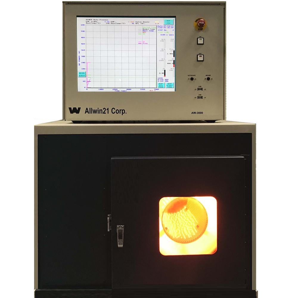
Desktop Semi-Auto Plasma Asher, Cleaning & Etcher System
Cost-Effective 13.56 MHz Plasma Cleaning Platform for Semiconductor Batch Processing
Production-Proven Reactor
Built on decades of worldwide dry plasma asher , etcher production and semiconductor cleaning experience across fabs, universities, MEMS, packaging, and R&D labs.
Customer Gets:
Lower technology risk, practical production operation, and faster transition into real process applications.
Modernized Hardware
Allwin21 improvements include modern air-cooled RF system, MFC gas delivery, Baratron pressure measurement, throttle valve pressure control, simplified maintenance access, and optional EOP function.
Customer Gets:
Better serviceability, improved reliability, reduced obsolete hardware risk, and more flexible process development.
Process-Oriented Software
AW software supports recipe control, process curve display, diagnostics, calibration, subsystem testing, process monitoring, and optional EOP integration.
Customer Gets:
Easier process setup, faster troubleshooting, better engineering visibility, and stronger fab engineering support.
The AW-B3000 batch barrel plasma asher is a manual load RF plasma cleaning and photoresist strip system for semiconductor fabs, MEMS, packaging, national labs, and university nano fabs requiring production-proven dry cleaning capability with practical operation and low cost of ownership.


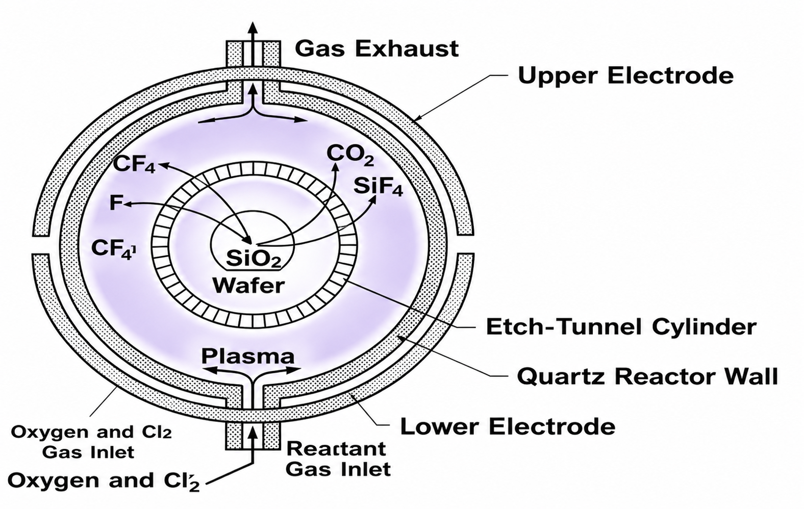 The AW-B3000 is based on a production-proven barrel plasma reactor architecture widely used for semiconductor photoresist strip, plasma cleaning, and general dry process applications in semiconductor manufacturing environments.
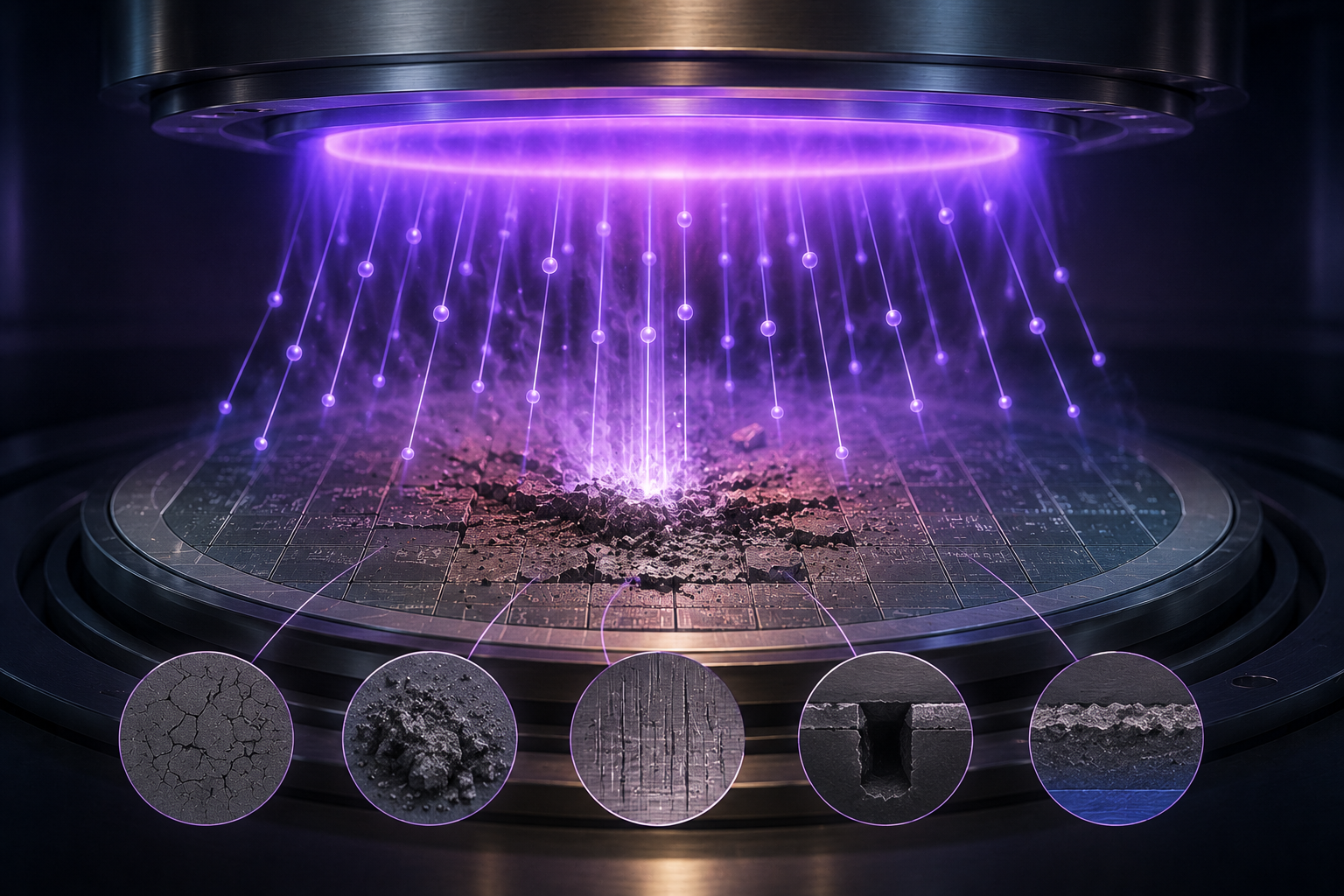
In barrel plasma processing, RF plasma is generated inside the quartz reactor chamber while reactive species flow around the process region for batch plasma cleaning and photoresist removal. This process philosophy has been widely used for semiconductor fabs, MEMS devices, packaging applications, university nano fabs, and long plasma cleaning processes where practical production operation and lower cost of ownership are important.
The barrel plasma reactor concept is especially suitable for thick photoresist stripping, general wafer cleaning, flexible substrate loading configurations, and longer plasma process applications where ultra-tight downstream plasma uniformity is not the primary requirement.
Allwin21 modernizes the platform with updated RF hardware, MFC gas delivery, Baratron pressure measurement, throttle valve pressure control, industrial PC control architecture, process-oriented software, and long-term service support while preserving the production-proven barrel plasma reactor philosophy.
1. Production-Proven Barrel Plasma Platform
The AW-B3000 is designed for semiconductor fabs, MEMS, packaging, national labs, and university nano fabs that need a practical batch plasma asher for photoresist strip, dry cleaning, and long plasma cleaning processes.
The barrel plasma reactor architecture is production-proven and well suited for thick photoresist removal, flexible substrate loading, and general plasma cleaning applications where ultra-tight downstream plasma uniformity is not the primary requirement.
Customer Gets:
- Production-proven batch plasma cleaning platform
- Lower technology risk
- Practical operation and low cost of ownership
- Flexible support for samples, wafers, and custom carriers
2. Modernized Allwin21 Hardware
Allwin21 modernizes the platform with modern air-cooled RF hardware, MFC gas delivery, Baratron pressure measurement, throttle valve pressure control, simplified maintenance access, and optional EOP function.
The modernized architecture helps reduce obsolete hardware dependency while improving serviceability, process flexibility, and long-term equipment support.
Customer Gets:
- Modern RF and gas control architecture
- Pressure measurement and throttle valve control
- Reduced obsolete hardware risk
- Easier maintenance and troubleshooting
3. Flexible Batch Process Capability
The AW-B3000 supports small samples and wafers up to 8 inches depending on fixture and carrier configuration. Quartz boats, trays, and custom loading fixtures can be configured for different substrate shapes, sizes, and thicknesses.
This makes the system especially useful for R&D, MEMS, packaging, compound semiconductor support processes, and applications with different photoresist thicknesses or long ash times.
Customer Gets:
- Small sample to wafer batch processing
- Support for thick photoresist strip
- Flexible quartz boat and tray options
- Practical process development capability
4. Process-Oriented AW Software
Allwin21 AW software supports recipe editing, process curve display, process monitoring, diagnostics, calibration functions, subsystem testing, and optional EOP integration.
The software is designed to help process engineers and equipment engineers set up recipes, monitor process behavior, troubleshoot issues, and support long-term fab operation.
Customer Gets:
- Easier recipe setup
- Real-time process visibility
- Faster troubleshooting capability
- Improved long-term engineering support
1. What Are Plasma Strip, Asher, and Descum Processes?
 Plasma strip, asher, and descum processes are used to remove photoresist, polymer residue, organic contamination, or surface residue after lithography, etch, implant, deposition, or other semiconductor manufacturing processes.
Although these terms are widely used throughout the semiconductor industry, their meanings are not always absolute. In many practical applications, strip, ash, and descum processes are better understood as different process windows, process targets, and process priorities rather than completely separate technologies.
In general, stripper processes are typically associated with thicker photoresist removal and may use relatively higher RF power, higher temperature, and higher gas flow for faster removal rate and higher throughput. Descum processes are usually associated with very thin residue removal, light polymer cleaning, or gentle surface preparation where lower RF power, lower temperature, lower gas flow, better uniformity, lower damage, or better repeatability may become more important. Asher processes are often positioned between these process conditions depending on application requirements.
There is no single “best” plasma strip, asher, or descum condition for all applications. Higher removal rate may improve throughput, but may also reduce process uniformity or repeatability depending on wafer size, pattern density, substrate sensitivity, chamber condition, and process chemistry. Additional gases such as N₂ are sometimes used to increase process rate for selected applications when maximum uniformity is not the primary target.
For this reason, customers should first clearly understand their actual process targets and acceptable process window before comparing plasma systems or configurations. Different applications may prioritize different balances between removal rate, uniformity, repeatability, throughput, wafer sensitivity, RF damage, process temperature, automation level, and long-term process stability. The appropriate plasma equipment configuration should therefore be selected based on actual application requirements rather than only comparing a single specification such as maximum asher rate.
2. Why Production Fabs Use Only a Few Plasma Platforms
There are many plasma strip, asher, and descum equipment suppliers in the semiconductor industry. Many systems may appear similar in brochure specifications or basic plasma capability. However, actual production fabs often standardize around only a limited number of plasma platforms and models.
This is because production fabs usually evaluate plasma equipment based on much more than whether the plasma can simply remove photoresist or residue. In actual manufacturing environments, process repeatability, chamber stability, wafer handling reliability, low RF damage behavior, process transfer stability, uptime, maintenance strategy, spare-parts continuity, and long-term engineering support may become more important than a single headline specification such as maximum asher rate.
For this reason, many fabs continue using the same qualified plasma platforms for years after process qualification. In many cases, fabs may even prefer to continue using existing familiar platforms instead of changing to a theoretically “better” or newer system because process requalification, chamber matching, engineering retraining, spare-parts changes, software differences, or unknown long-term process behavior may introduce additional production risk.
Many smaller or newer equipment suppliers may still be suitable for university, laboratory, pilot-line, or selected development applications. However, long-term production fabs often require broader engineering experience, larger installed production base, long-term field feedback, stable spare-parts support, mature service capability, and years of continuous engineering improvement before a plasma platform becomes widely accepted for production manufacturing.
Customers evaluating plasma strip, asher, or descum equipment should therefore focus not only on website descriptions, brochure specifications, or short-term demonstrations. Important topics may also include actual application history, repeatability, low RF damage behavior, process stability, long-term support capability, maintenance strategy, spare-parts continuity, wafer handling stability, process transfer experience, and long-term supplier support capability.
Plasma strip, asher, and descum equipment should therefore be selected based on actual process requirements, acceptable process window, throughput target, uniformity target, wafer sensitivity, repeatability requirements, automation requirements, and long-term production expectations. Correct platform and configuration selection can remain important for many years after initial process qualification.
3. Low RF Damage and Why Downstream Plasma Matters
 Low RF damage has become an important discussion in many semiconductor plasma processes, especially for compound semiconductor, III-V, photonics, RF, MEMS, detector, and other sensitive device applications.
Industry discussions related to plasma damage often involve topics such as ion bombardment, charging effects, surface modification, leakage behavior, interface damage, trap-state generation, repeatability, wafer sensitivity, and long-term process stability depending on device structure and process conditions.
For this reason, many customers now specifically discuss low RF damage, low ion bombardment, downstream plasma, remote plasma, gentle descum, and low-temperature plasma processing when evaluating plasma strip, asher, descum, plasma clean, or selected plasma etch applications.
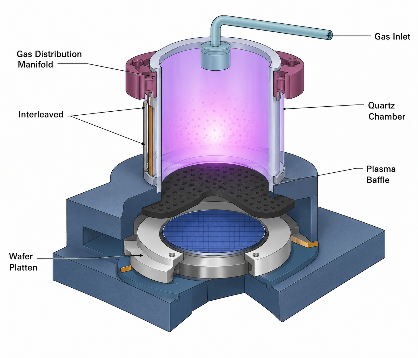
In a downstream plasma architecture, plasma is generated away from the wafer process area. Reactive neutral species flow into the process chamber while direct plasma exposure and direct ion bombardment on the wafer surface are reduced compared with many direct plasma configurations.
This is one reason downstream plasma platforms are often selected for low-damage strip, asher, descum, plasma clean, and selected plasma etch applications where wafer sensitivity, repeatability, surface condition, and long-term process stability may be important.
4. Legacy Plasma Tool Support and Process Continuity
 Many compound semiconductor fabs are still running downstream plasma ashers, descum tools, and plasma etch systems originally installed in the 1980s and 1990s. These tools often remain in production because the process already works, the recipes are already qualified, and the chamber behavior is already understood by the fab engineering team.
At the same time, many fabs are now dealing with increasing sustaining pain from legacy plasma platforms. Old PCs may no longer boot reliably. Controllers, PCBs, RF electronics, motion hardware, and OEM-specific modules may already be obsolete or difficult to replace. In some fabs, engineers keep retired systems only for spare parts. One failed PCB or controller can sometimes stop production for days or weeks.
The difficult part is that many fabs cannot simply replace these systems with completely different plasma platforms. The downstream plasma behavior, low RF damage characteristics, wafer handling behavior, process repeatability, and qualified process window may already be tied closely to production yield and long-term fab experience.
As a result, many compound semiconductor fabs today usually follow two practical paths. One path is to purchase rebuilt, reformed, or refurbished plasma platforms using modern controllers, modern software, updated electronics, and currently supportable components while maintaining similar plasma process philosophy and familiar chamber behavior. The second path is to upgrade existing legacy systems using modern control hardware, software, networking capability, RF/control electronics, and industrial computer architecture while preserving the original qualified chamber and process behavior.
This is one reason why modern electronics, modern components, improved wafer transfer, software support, diagnostics, networking capability, and long-term spare-parts support have become increasingly important topics in many compound semiconductor fabs still operating legacy downstream plasma platforms today.
5. Why Semiconductor Front-End Equipment Purchasing Is Different
 Semiconductor front-end process equipment is expensive, and the cost of making the wrong decision can be very high. A wrong equipment choice may affect qualification, production plans, engineering resources, and even the entire project direction.
It is also technically complex. Many specifications depend on process conditions, wafer materials, recipes, facility conditions, and measurement methods. The same result achieved in one fab may not be achievable in another fab.
This is why experienced suppliers ask key RFQ questions early.
| Item | AW-B3000 Specification |
|---|---|
| Quartz Reactor Size | 12-inch diameter × 23-inch depth. |
| Substrate / Wafer Size | Small samples to 8-inch round wafers.
More detailsCustomer is responsible for suitable quartz trays, quartz boats, or custom substrate holders based on substrate size, shape, thickness, and process application. For best process consistency, substrate loading is preferably centered within the quartz reactor.
|
| Substrate Thickness | Any thickness with a suitable holder or carrier. |
| Wafer Transfer | Manual load / unload. |
| RF Power | 600 W, 1000 W, or 1200 W air-cooled RF generator, 13.56 MHz.
More detailsFinal RF power configuration depends on quotation, process application, and system configuration.
|
| Temperature | No active temperature control.
More detailsReactor internal temperature depends on RF power, process pressure, gas chemistry, loading condition, and recipe time. Optional thermocouple monitoring measures reactor/chamber temperature only and does not directly measure substrate temperature. Some customers use N₂ plasma preheating before O₂ plasma strip or descum processes.
|
| Gas Lines | 1–4 gas lines with MFCs.
More detailsTypical process gas is O₂. Additional gas configurations may be available depending on application requirements.
|
| Typical MFC Configuration | 5 SLM O₂ or 500 SCCM O₂.
More detailsFinal MFC range and gas configuration depend on process application, recipe requirement, and quotation.
|
| Base Pressure | Typically ~30–50 mTorr.
More detailsBase pressure depends on vacuum pump condition, chamber condition, seal condition, gas configuration, and facility environment.
|
| Process Pressure | Typical process pressure around 3.0–4.5 Torr.
More detailsStandard reference processes commonly use approximately 3.75 Torr. Actual process pressure depends on recipe, gas flow, RF power, substrate condition, and application requirements.
|
| Typical Ash Rate | 0–0.2 µm/min typical, process dependent.
More detailsActual ash rate depends on photoresist type, wafer temperature, RF power, chamber pressure, gas chemistry, loading condition, and process recipe.
|
| Ash Uniformity | 5% to 25%. Application dependent.
More detailsActual ash uniformity depends on substrate size, loading position, holder design, resist thickness, RF power, pressure, gas flow, recipe time, and whether a Faraday cage configuration is used.
|
| Particle Performance | <0.05/cm² @ 0.3 µm or greater typical.
More detailsParticle performance depends on wafer condition, chamber cleanliness, quartzware condition, process recipe, loading method, and customer metrology method.
|
| RF Damage Control | Low plasma damage process capability with optional Faraday cage configuration.
More detailsUsing a Faraday cage configuration can create a downstream-style plasma environment that helps reduce direct ion bombardment and plasma damage on sensitive substrates.
|
| Selectivity | >1000:1 typical, process dependent.
More detailsActual selectivity depends on substrate material, photoresist chemistry, plasma condition, gas chemistry, RF power, pressure, and process recipe.
|
| MTBF / MTTA / MTTR | 450 hr / 100 hr / 3.5 hr reference values.
More detailsReliability values are historical platform reference values and depend on system configuration, maintenance condition, process environment, and user operation.
|
| Uptime | 95% reference value. |
| Item | AW-B3000 Standard Configuration |
|---|---|
| AW-B3000 Controller with Touchscreen Monitor | AW-B3000 controller with 1–4 gas lines with MFCs, integrated industrial PC, touchscreen GUI, control electronics, EMO, safety interlocks, breakers, relays, DC power distribution, and rear-panel interface connections to the reactor main body. |
| AW-B3000 Main Body | AW-B3000 main body includes cylindrical quartz reactor chamber, chamber door assembly, RF matching network, MKS Baratron pressure measurement, and throttle valve pressure control architecture. |
| RF Generator | 600 W, 1000 W, or 1200 W air-cooled RF generator, 13.56 MHz. |
| Gas System | One gas line with O₂ MFC (5 SLM or 500 SCCM typical), pneumatic valves, shut-off valve, and application-specific gas routing configuration integrated into the AW-B3000 controller. |
| Pressure Control | MKS Baratron pressure measurement with throttle valve pressure control architecture integrated into the AW-B3000 controller. |
| Software | Allwin21 proprietary process-engineer-oriented software with recipe control, real-time process monitoring, diagnostics, calibration functions, manual operation, subsystem testing, data logging, alarm history, maintenance support, and optional EOP integration. |
| Option | Description |
|---|---|
| Additional Gas Lines | Optional additional gas lines for O₂, N₂, or other process gases.
More detailsThe standard AW-B3000 configuration typically includes one O₂ MFC with common ranges such as 5 SLM or 500 SCCM depending on application requirements. The system can be configured with up to 4 gas lines with customer-selectable MFC ranges for different plasma cleaning, photoresist strip, residue removal, descum, or surface treatment applications.
Additional O₂ gas lines, optional N₂ gas lines, and other process gases can be reviewed depending on process requirements. Optional N₂ configuration may help preheat the reactor before plasma strip process or improve ash rate for some applications. Higher process rate may also affect process uniformity depending on substrate size, loading condition, chamber condition, and recipe. |
| Advanced EOP Monitoring | Optional plasma process monitoring and alarm capability for additional process visibility and engineering support. |
| Customized Substrate Holders | Optional quartz trays, quartz boats, quartz plates, and customized substrate holders for different substrate sizes, shapes, thicknesses, and loading configurations. |
| Aluminum Chamber Configuration | Optional aluminum chamber configuration instead of cylindrical quartz reactor for selected plasma etch applications. |
| GEM/SECS Interface | Optional GEM/SECS factory communication interface.
More detailsSupports communication with factory automation systems, fab host systems, and MES integration when required.
|
| Vacuum Pump | Mechanical pump or dry pump configuration can be reviewed depending on application requirements.
More detailsAllwin21 strongly recommends that customers select vacuum pumps based on their existing fab or laboratory pump standards whenever possible. Many fabs and laboratories prefer to standardize pump suppliers, pump models, spare parts, fittings, maintenance procedures, and support infrastructure across multiple equipment platforms for easier long-term maintenance and facility support.
Using different pump suppliers or pump models across different equipment platforms may increase future maintenance complexity, spare-parts management burden, support difficulty, and long-term operating cost. After receiving the equipment purchase order, Allwin21 can provide corresponding facility and vacuum pump requirement information, including recommended pumping capability, pressure range, cooling requirements, exhaust requirements, and interface recommendations. Allwin21 can also recommend suitable pump models if requested. If bundled pump purchasing is required for project, grant, or funding purposes, pump supply can be reviewed case by case. |
| Faraday Cage Configuration | Optional Faraday cage configuration for reduced plasma damage processing on selected sensitive substrate applications.
More detailsUsing a Faraday cage configuration can create a downstream-style plasma environment that helps reduce direct ion bombardment and plasma damage on sensitive substrates.
|
| Spare Parts / Service | Optional spare parts kit, installation, training, process support, engineering service, and long-term maintenance support. |
| Electrical | 190–240 VAC, single phase, 30A, 50/60 Hz.
More detailsNEMA L6-30P plug supplied. Please confirm facility power configuration before order placement.
|
| Process Gases | O₂ up to 5 SLM typical and N₂ up to 1 SLM typical.
More detailsFiltered facility gas supply required. Final gas type, pressure, and flow configuration depend on process application and quotation.
|
| Purge Gas / CDA | N₂ purge gas: 20 psi typical. CDA or dry N₂: 80 psi typical.
More detailsFacility-supplied filtered dry nitrogen or clean dry air (CDA) is required for pneumatic valve operation and purge functions.
|
| Facility Exhaust | 100 CFM at 1″ water-column static pressure.
More detailsFacility exhaust connection is required. Final exhaust configuration should be confirmed before installation.
|
| Process Vacuum | Minimum recommended pumping speed: 32 CFM.
More detailsMechanical pump or dry pump configuration can be reviewed depending on process application and customer facility standards.
|
| Item | Information |
|---|---|
| Equipment Dimensions | Approx. 27″ W × 34″ D × 45″ H |
| AW-B3000 Net Weight | Approximately 300 lbs |
| Shipping Crate Dimensions | 40″ W × 55″ D × 55″ H |
| Shipping Weight | Approximately 500 lbs |
AW-B3000 Desktop Semi-Auto Plasma Asher & Cleaning System
- Product photos and descriptions are for general reference only.
- Final configuration, specifications, options, and facility requirements shall be confirmed by official Allwin21 quotation and technical documentation.
- Process rate, residue-removal performance, and uniformity are application dependent.
- Facility requirements depend on final configuration and customer process requirements.
- OEM trademarks belong to their respective owners.