
AW-303R Isotropic Downstream Plasma Etcher System
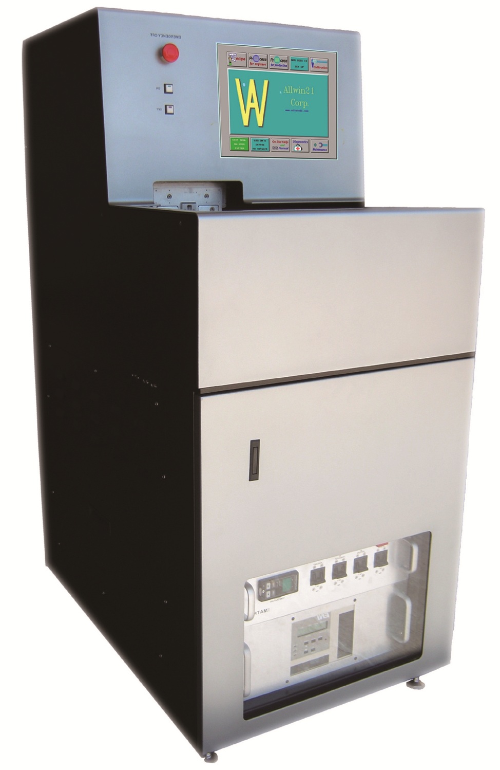
Automatic Downstream Production Isotropic Plasma Etcher System
Production-Oriented Automatic Downstream Etcher for 2“~6” High-Value Wafer Processing
Production-Proven Reactor
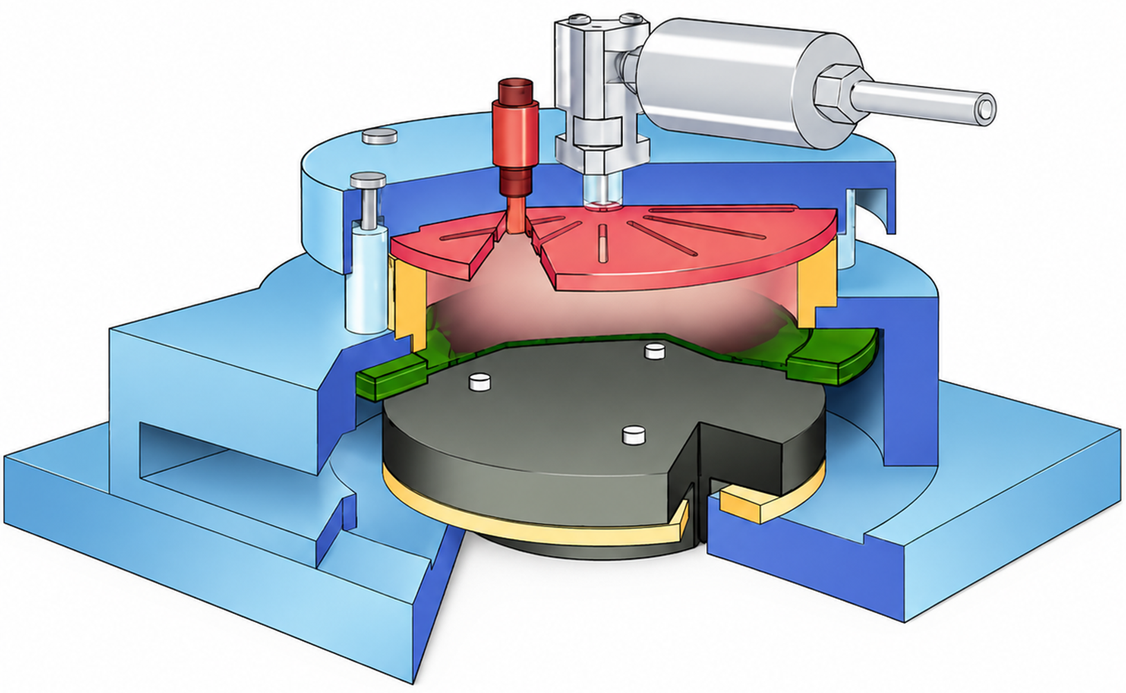
Downstream plasma architecture separates plasma generation from the wafer process area to reduce direct ion bombardment on sensitive substrates.
Customer Gets:
Low-damage process capability and stable production-proven reactor philosophy.
Modernized Hardware
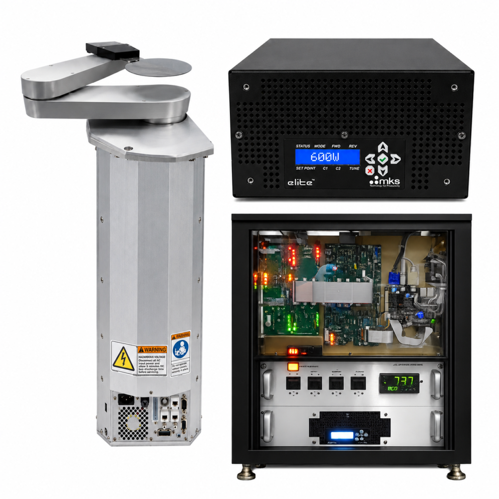
Integrated 3-axis robot, fixed cassette station, wafer centering station, modern RF system, and simplified control electronics.
Customer Gets:
Improved wafer handling reliability, easier maintenance, and reduced obsolete hardware risk.
Process-Engineer Software
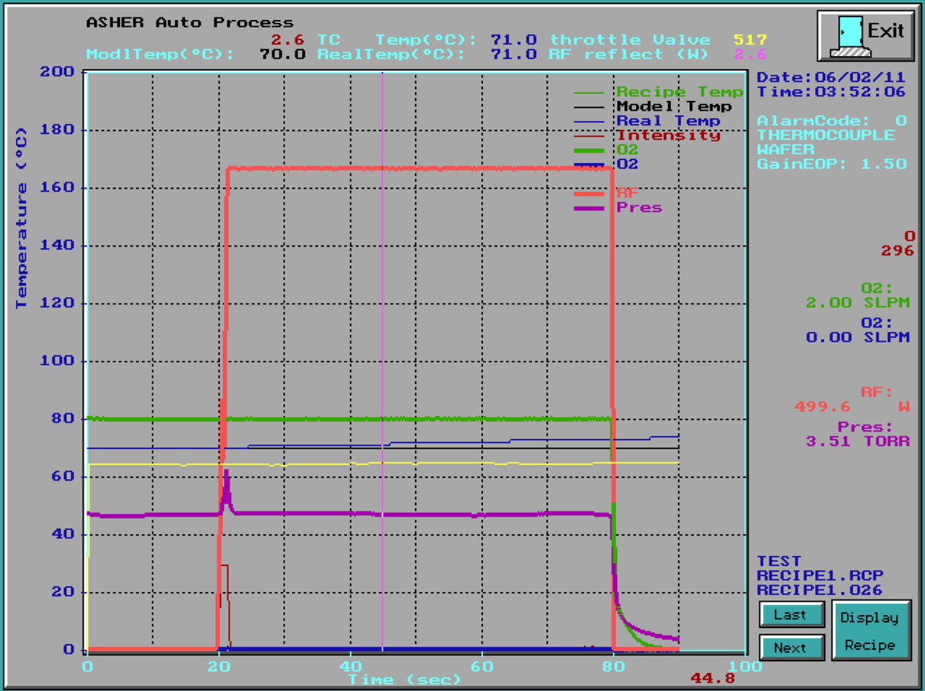
Recipe control, process curve display, diagnostics, software calibration, subsystem testing, and optional EOP process protection.
Customer Gets:
Easier process setup, faster troubleshooting, and stronger fab engineering support.
The AW-303R is designed for compound semiconductor fabs, national laboratories, and advanced university nano fabs where downstream plasma processing, wafer handling reliability, and repeatable isotropic plasma etching directly affect process stability and yield. Many customers use the AW-303R to replace selected wet etch processes where chemical handling, process control, repeatability, and waste disposal become significant concerns.

 The AW-303R is based on a production-proven downstream plasma reactor architecture widely used for semiconductor Polysilicon, silicon nitride, silicide, polyimide, BCB, backside etch, Silicon dioxide, oxide contact, via, pad etch, passivation, dielectric etch, resist / SOG planarization.
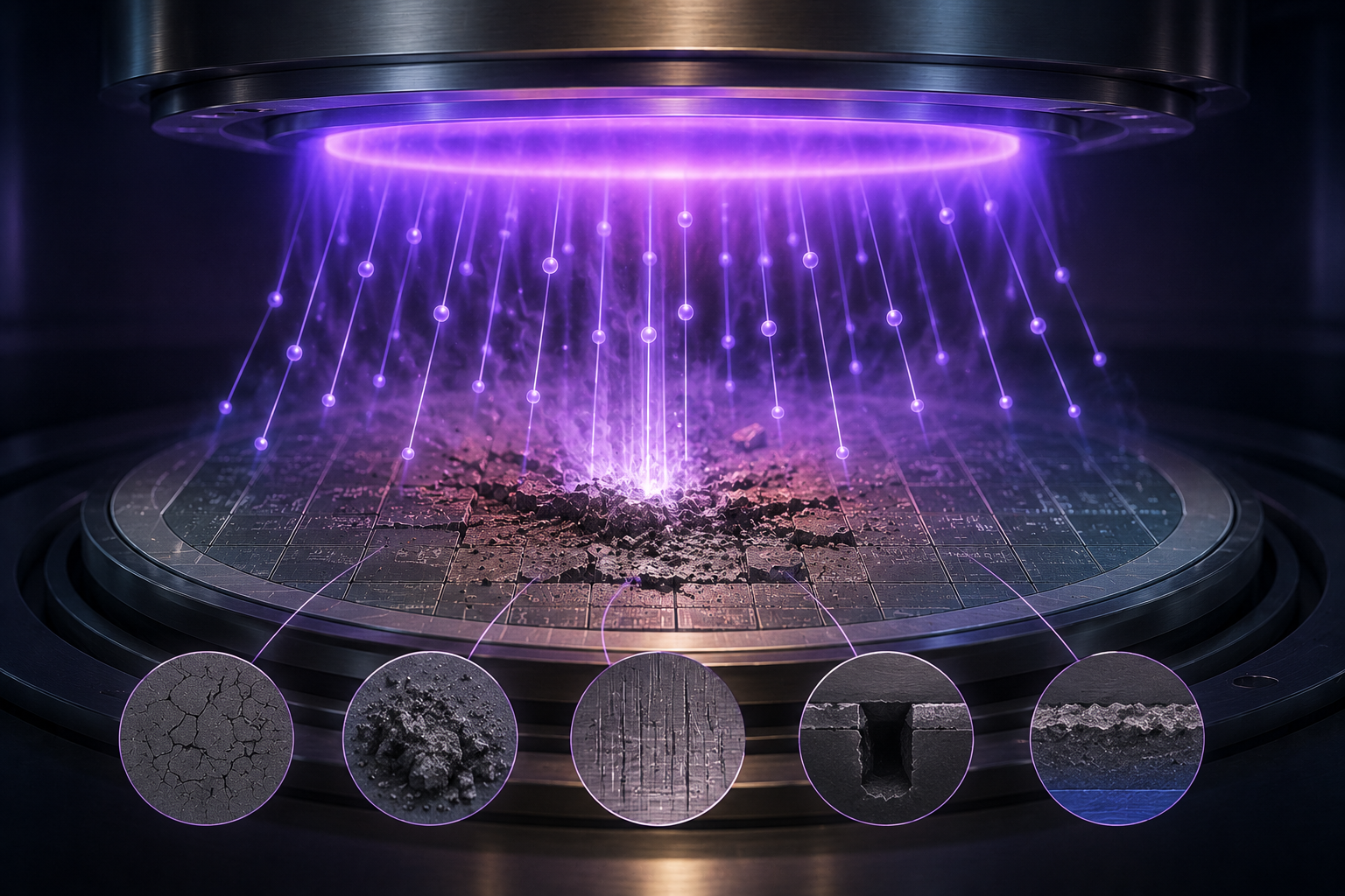
In downstream plasma processing, plasma is generated in the upper ceramic-aluminum plasma region while reactive species flow into the wafer process chamber below. This architecture helps reduce direct ion bombardment and plasma exposure on the wafer surface compared with many direct plasma configurations.
The downstream process concept is widely used for compound semiconductor, photonics, RF device, and other applications where low process damage, residue control, repeatability, and stable wafer handling are important.
Allwin21 modernizes the platform with updated robotic wafer handling, simplified electronics architecture, industrial PC control, modern RF system, process-oriented software, and long-term service support while preserving the proven downstream plasma process philosophy.
1. Production-Proven Isotropic Plasma Etcher Platform
The AW-303R is designed for compound semiconductor fabs, national labs, and advanced university nano fabs where repeatable downstream plasma etcher, wafer handling reliability, low RF damage directly affect process stability and yield.
The downstream plasma architecture separates plasma generation from the wafer process area to help reduce direct ion bombardment on sensitive substrates.
Customer Gets:
- Production-oriented Isotropic Plasma Etcher platform
- Stable repeatable wafer preparation
- Low-damage downstream plasma processing
- Long-term fab process supportability
2. Modernized Allwin21 Hardware
Allwin21 modernizes the platform with integrated 3-axis robotic wafer handling, fixed cassette station, wafer centering station, modern RF system, simplified electronics architecture, industrial PC control, and updated subsystem architecture.
The modernized architecture helps reduce obsolete hardware dependency while improving maintenance and long-term serviceability.
Customer Gets:
- Integrated robotic wafer handling
- Reduced obsolete hardware risk
- Simplified maintenance architecture
- Modernized subsystem control
3. Process-Engineer Software
Allwin21 control software was designed around real semiconductor process and equipment engineering requirements, not just machine operation.
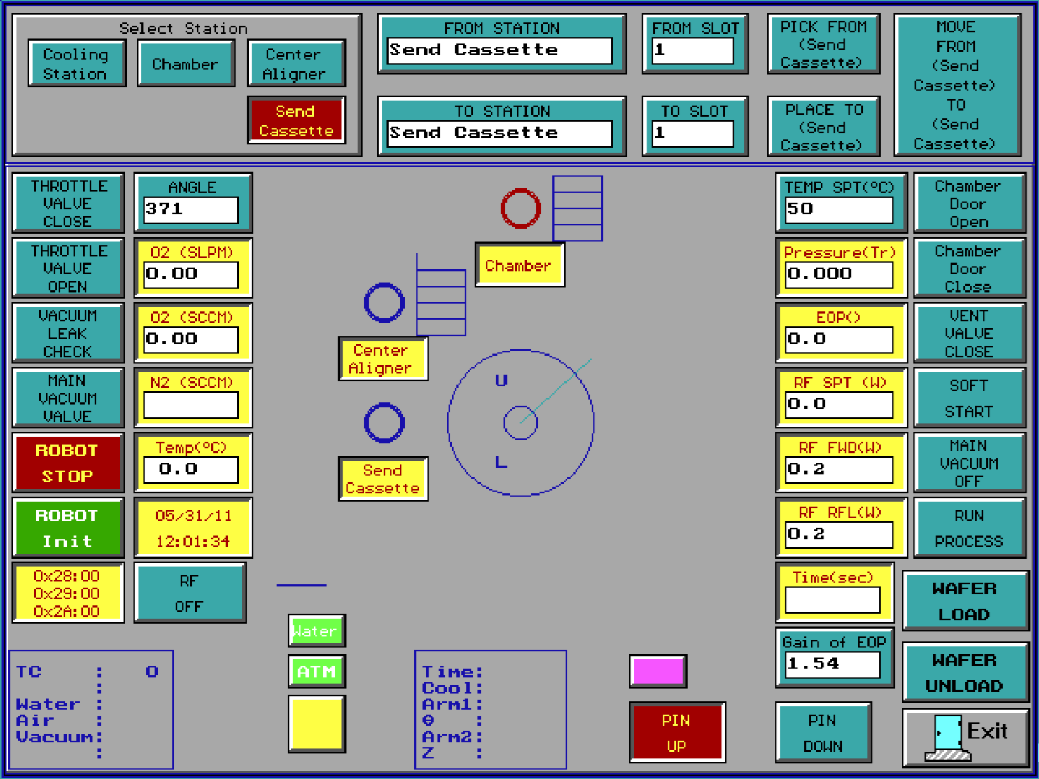
The software supports recipe editing, process curve display, subsystem diagnostics, calibration functions, manual operation testing, and robot teach functions directly through the software environment.
Customer Gets:
- Easier process setup
- Software-based calibration support
- Faster troubleshooting capability
- Improved long-term maintenance support
4. Compound Semiconductor Application Experience
The AW-303R has been used for compound semiconductor applications where downstream plasma etcher, and low-damage downstream plasma processing are important for sensitive substrates and device structures.
Allwin21 has practical experience supporting III-V and compound semiconductor customers, including InP-related applications, where wafer handling, process repeatability, and low RF damage control are critical.
Customer Gets:
- Experience with compound semiconductor applications
- Support for InP, GaAs, GaN, SiC, GaInP and other sensitive substrate processes
- Low-damage downstream plasma processing approach
- Process support based on real customer applications
All trademarks belong to their respective owners.
1. What Are Isotropic Plasma Etch Processes?
Isotropic plasma etch processes are widely used throughout the semiconductor industry whenever material removal is required in multiple directions rather than primarily in a vertical direction. These processes are commonly used for selected oxide, nitride, polymer, sacrificial-layer, residue-removal, surface-cleaning, MEMS release, compound semiconductor, photonics, detector, and other specialty semiconductor applications.
Although isotropic plasma etching is often discussed as a single process category, actual applications can vary significantly depending on material type, device structure, selectivity requirements, acceptable undercut, wafer sensitivity, and process objectives. In many practical situations, isotropic plasma etching is better understood as a broad family of process windows rather than a single technology.
Some applications prioritize faster etch rate and higher throughput, while others focus on selectivity, repeatability, low RF damage, surface condition, uniformity, endpoint behavior, or protection of sensitive device structures. The optimum balance often depends on wafer material, layer stack, chamber condition, process chemistry, pressure, RF power, and temperature.
There is no single “best” isotropic plasma etch condition for all applications. Higher etch rate may improve throughput, but may also affect selectivity, profile behavior, undercut characteristics, uniformity, repeatability, or surface condition depending on the process chemistry and material system. Different gases and process conditions may also be selected depending on whether the primary objective is material removal, cleaning, release, residue reduction, or process integration.
For this reason, customers should first clearly understand their actual process targets and acceptable process window before comparing plasma etch systems or configurations. Different applications may prioritize different balances between etch rate, selectivity, repeatability, throughput, wafer sensitivity, RF damage, process temperature, automation level, maintenance requirements, and long-term process stability.
2. Why Production Fabs Use Only a Few Plasma Platforms
There are many plasma equipment suppliers in the semiconductor industry. Many systems may appear similar in brochure specifications or basic plasma capability. However, actual production fabs often standardize around only a limited number of plasma platforms and models.
This is because production fabs usually evaluate plasma equipment based on much more than whether the plasma can simply etch the target material. In actual manufacturing environments, process repeatability, chamber stability, wafer handling reliability, low RF damage behavior, process transfer stability, uptime, maintenance strategy, spare-parts continuity, and long-term engineering support may become more important than a single headline specification such as maximum etch rate.
For this reason, many fabs continue using the same qualified plasma platforms for years after process qualification. In many cases, fabs may even prefer to continue using existing familiar platforms instead of changing to a theoretically better or newer system because process requalification, chamber matching, engineering retraining, spare-parts changes, software differences, or unknown long-term process behavior may introduce additional production risk.
Many smaller or newer equipment suppliers may still be suitable for university, laboratory, pilot-line, or selected development applications. However, long-term production fabs often require broader engineering experience, larger installed production base, long-term field feedback, stable spare-parts support, mature service capability, and years of continuous engineering improvement before a plasma platform becomes widely accepted for production manufacturing.
Customers evaluating plasma etch equipment should therefore focus not only on website descriptions, brochure specifications, or short-term demonstrations. Important topics may also include actual application history, repeatability, low RF damage behavior, process stability, long-term support capability, maintenance strategy, spare-parts continuity, wafer handling stability, process transfer experience, and long-term supplier support capability.
Plasma etch equipment should therefore be selected based on actual process requirements, acceptable process window, throughput target, uniformity target, wafer sensitivity, repeatability requirements, automation requirements, and long-term production expectations.
3. Low RF Damage and Why Downstream Plasma Matters
Low RF damage has become an important discussion in many semiconductor plasma processes, especially for compound semiconductor, III-V, photonics, RF, MEMS, detector, and other sensitive device applications.
Industry discussions related to plasma damage often involve topics such as ion bombardment, charging effects, surface modification, leakage behavior, interface damage, trap-state generation, repeatability, wafer sensitivity, and long-term process stability depending on device structure and process conditions.
For this reason, many customers now specifically discuss low RF damage, low ion bombardment, downstream plasma, remote plasma, low-damage plasma etch, and low-temperature plasma processing when evaluating isotropic plasma etch applications.
In a downstream plasma architecture, plasma is generated away from the wafer process area. Reactive neutral species flow into the process chamber while direct plasma exposure and direct ion bombardment on the wafer surface are reduced compared with many direct plasma configurations.
This is one reason downstream plasma platforms are often selected for low-damage plasma etch, plasma clean, MEMS release, compound semiconductor processing, and other applications where wafer sensitivity, repeatability, surface condition, and long-term process stability may be important.
4. Legacy Plasma Tool Support and Process Continuity

Many semiconductor fabs are still running downstream plasma etch systems originally installed in the 1980s and 1990s. These tools often remain in production because the process already works, the recipes are already qualified, and the chamber behavior is already understood by the fab engineering team.
At the same time, many fabs are now dealing with increasing sustaining pain from legacy plasma platforms. Old PCs may no longer boot reliably. Controllers, PCBs, RF electronics, motion hardware, and OEM-specific modules may already be obsolete or difficult to replace. In some fabs, engineers keep retired systems only for spare parts. One failed PCB or controller can sometimes stop production for days or weeks.
The difficult part is that many fabs cannot simply replace these systems with completely different plasma platforms. The downstream plasma behavior, low RF damage characteristics, wafer handling behavior, process repeatability, and qualified process window may already be tied closely to production yield and long-term fab experience.
As a result, many semiconductor fabs today usually follow two practical paths. One path is to purchase rebuilt, reformed, or refurbished plasma platforms using modern controllers, modern software, updated electronics, and currently supportable components while maintaining similar plasma process philosophy and familiar chamber behavior. The second path is to upgrade existing legacy systems using modern control hardware, software, networking capability, RF/control electronics, and industrial computer architecture while preserving the original qualified chamber and process behavior.
This is one reason why modern electronics, modern components, improved wafer transfer, software support, diagnostics, networking capability, and long-term spare-parts support have become increasingly important topics in many semiconductor fabs still operating legacy downstream plasma platforms today.
5. Why Semiconductor Front-End Equipment Purchasing Is Different
Semiconductor front-end process equipment is expensive, and the cost of making the wrong decision can be very high. A wrong equipment choice may affect qualification, production plans, engineering resources, and even the entire project direction.
It is also technically complex. Many specifications depend on process conditions, wafer materials, recipes, facility conditions, and measurement methods. The same result achieved in one fab may not be achievable in another fab.
This is why experienced suppliers ask key RFQ questions early.
Budget Range
Budget helps quickly narrow the suitable equipment level and avoid wasting time on the wrong platform.
Mature Fab Information
Existing equipment platforms, previous successful tools, current pain points, desired improvements, wafer size, throughput, and production plans help define the safest equipment direction.
Startup Fab Information
Where the technology was developed, what equipment was previously used successfully, what limitations existed, and what improvements are truly needed are often the most important starting points.
Complete and correct information helps both sides identify the most realistic equipment direction much faster and improves communication efficiency significantly.
| Item | AW-303R Specification |
|---|---|
| Wafer Size | 2”, 3”, 4”, 5”, 6” round wafers.
More detailsSubstrate capability includes 2”, 3”, 4”, 5” and 6” round wafers. Multiple wafer sizes may be supported without hardware change depending on final cassette, chuck, and handling configuration.
|
| Wafer Thickness | 200–1000 µm.
More detailsCustomized handling review may be required for thin, fragile, bowed, or carrier-mounted substrates.
|
| Wafer Transfer | Automatic single-wafer transfer with integrated 3-axis robot.
More detailsIncludes fixed cassette station and wafer centering / aligner configuration.
|
| RF Power | Maximum 650W. Typical RF power 75~325W. 13.56 MHz. |
| Chuck Temperature | 20–120°C.
More detailsActual wafer temperature depends on RF power, process duration, wafer contact condition, substrate material, and recipe.
|
| Temperature Control | ±2°C typical.
More detailsTemperature performance depends on chuck condition, wafer backside condition, process pressure, RF power, and process recipe.
|
| Gases Flow | Typical gas flow rates: 10-60 SCCM NF3; 0-50 SCCM O2; 0-120 SCCM He.
More detailsTypical gases include NF3, O2 and He. Additional gas configurations may be available depending on application.
|
| Base Pressure | Typically 20–30 mTorr.
More detailsBase pressure depends on vacuum pump condition, chamber condition, seal condition, gas configuration, and facility environment.
|
| Process Pressure | Typical process pressure around 0.50–1.80 Torr. |
| Typical Etcher Rate | >2000 Å/min. T.h. Oxide; >16,000 Å/min. LPCVD Nitride
More detailsEtcher rate depends on etching materials, wafer temperature, RF power, chamber pressure, gas flow, gas chemistry, and process recipe condition.
|
| Etcher Uniformity | <±5%~8% typical, process dependent.
More detailsActual Etcher uniformity depends on substrate size, etcher materials, etcher rates, chuck temperature, RF power, pressure, and recipe condition.
|
| Particle Performance | <0.15/cm² @ 0.03 µm or greater typical.
More detailsActual particle performance depends on wafer condition, chamber cleanliness, process recipe, and metrology method.
|
| RF Damage Reference | CV: <0.1V from control; Mobile Ion: <1-2 E10; Vt: 0% total shift on 98% of points tested, no shift >5%.
More detailsActual RF damage performance depends on device structure, process pressure, RF power, wafer grounding condition, and recipe.
|
| Selectivity | High selectivity to PR (> 10: 1 Oxide : PR; SiN : Oxide), process dependent.
More detailsActual selectivity depends on substrate material, photoresist chemistry, plasma condition, and process recipe.
|
| MTBF / MTTA / MTTR | 450 hr / 100 hr / 3.5 hr typical.
More detailsReliability values are reference values from historical platform data and depend on maintenance condition and process environment.
|
| Uptime | 95% typical. |
| Item | AW-303R Standard Configuration |
|---|---|
| Main Chassis | Allwin21 AW-303R chassis with integrated industrial PC, touchscreen GUI, control electronics, EMO, interlocks, breakers, relays, AC/DC power distribution, and system wiring. |
| Etcher Reactor | Ceramic-Aluminum downstream plasma reactor with process chamber, chamber door assembly, and temperature-controlled chuck configuration. |
| Wafer Handling | Integrated 3-axis robotic wafer transfer, fixed cassette station, wafer centering station, cassette sensors, and wafer transfer architecture. |
| RF System | 300W or 600W or 650W air-cooled RF generator with Allwin21 RF matching and RF control architecture. |
| MFCs and Gas System | Typical gases: 200 SCCM NF3; 100 SCCM O2; 100 SCCM He. Other popular configurations can be CF₄ / O₂ / He; CHF₃ / O₂ / He; CF₄ / O₂ / Ar; SF₆ / O₂ / He for different applications. |
| Pressure Control | MKS Baratron pressure measurement and throttle valve pressure control architecture. |
| Temperature Control | Omega Modern chuck temperature controller with P.D.I. |
| Software | Allwin21 proprietary process-engineer-oriented software with recipe control, real-time process monitoring, diagnostics, calibration, manual operation, subsystem test functions, data logging, alarm history, maintenance support, and robot teach capability. |
| Option | Description |
|---|---|
| Additional Gas Lines | Optional additional gas lines with MFCs are available. |
| Advanced EOP Monitoring | Optional plasma-process monitoring and alarm capability for process monitoring support. |
| GEM/SECS Interface | Optional GEM/SECS factory communication interface.
More detailsSupports communication with factory automation systems and fab host / MES integration when required.
|
| SMIF Wafer Loader Port | Optional SMIF wafer loader port for automated wafer handling integration.
More detailsSupports integration with selected SMIF wafer loading systems for automated wafer transfer and factory automation applications. Allwin21 can supply selected SMIF wafer loader configurations, or customer-specified standard SMIF systems may be integrated depending on customer fab standards and configuration requirements. Allwin21 control software can communicate with compatible wafer loading systems through GEM/SECS communication architecture for integrated automatic operation and factory host / MES coordination depending on final configuration.
|
| Vacuum Pump | Mechanical pump, dry pump can be reviewed.
More detailsAllwin21 strongly recommends that customers select and purchase vacuum pumps based on their existing fab or laboratory pump standards whenever possible. Many fabs and laboratories prefer to standardize pump suppliers, pump models, spare parts, fittings, maintenance procedures, and support infrastructure across multiple equipment platforms for easier long-term maintenance and facility support.
Using different pump suppliers or pump models for different equipment may increase future maintenance complexity, spare-parts management burden, support difficulty, and long-term operating cost. After receiving the equipment purchase order, Allwin21 can provide the corresponding facility and vacuum pump requirement information, including recommended pumping capability, pressure range, cooling requirements, exhaust requirements, and interface recommendations. Allwin21 can also recommend suitable pump models if requested. If the customer requires bundled purchasing for project, grant, or funding reasons, Allwin21 can review pump supply case by case. |
| Spare Parts / Service | Optional spare parts kit, installation, training, process support, and engineering service. |
| Electrical | 190–240 VAC, single phase, 30A, 50/60 Hz.
More detailsNEMA L6-30P plug supplied. Please confirm facility power configuration before order placement.
|
| Cooling Water | 1 GPM house circulating supply at <23 ±2°C.
More detailsCustomer facility cooling water supply is required.
|
| Process Gases / Exhaust | Plumbed process gases: O₂ and N₂. Facility exhaust: 100 CFM at 1″ static pressure.
More detailsProcess gas and exhaust connections should be confirmed with final facility requirements before installation.
|
| Robot Vacuum Supply | 11.8″ Hg (-5.8 psi) / 0.1 CFM airflow.
More detailsVacuum supply is used for robotic wafer handling.
|
| Item | Information |
|---|---|
| Equipment Dimensions | Approx. 28″ W × 44″ D × 62″ H. |
| AW-303R Net Weight | Approximately 700 lbs |
| Shipping Crate Dimensions | 37″ W × 54″ D × 76″ H |
| Shipping Weight | Approximately 850 lbs |
| Facility Item | Typical Requirement |
|---|---|
| Electrical | 190–240 VAC, single phase, 30A, 50/60 Hz. |
| Process Gases | Typical plumbed process gases: O₂ and N₂. Additional gases are application dependent. |
| Cooling Water | Typical cooling water requirement: approximately 1 GPM house circulating supply at <23 ±2°C, configuration dependent. |
| Facility Exhaust | Typical facility exhaust: approximately 100 CFM at 1” static pressure, configuration dependent. |
| Robot Vacuum Supply | Typical vacuum supply for robot: approximately 11.8” Hg (-5.8 psi), 0.1 CFM airflow. |
- Product photos and descriptions are for general reference only.
- Final configuration, specifications, options, and facility requirements shall be confirmed by official Allwin21 quotation and technical documentation.
- Process rate, residue-removal performance, and uniformity are application dependent.
- Facility requirements depend on final configuration and customer process requirements.
- OEM trademarks belong to their respective owners.